

Sort by

Browsing
7-segment LED Display

CD4511 - BCD To 7 Segment Lat…
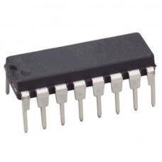
CD4511 - BCD To 7 Segment Latch Decoder Driver IC
The CD4511 IC types are BCD-to-7-segment latch decoder drivers constructed with CMOS logic and n-p-n bipolar transistor output devices on a single monolithic structure. These devices combine the low quiescent power dissipation and high noise immunity features of RCA CMOS with n-p-n bipolar output transistors capable of sourcing up to 25 MA. This capability allows the CD4511 types to drive LED's and other displays directly.
Lamp Test (LT)\, Blanking (BL)\, and Latch Enable or Strobe inputs are provided to test the display, shut off or intensity-modulated it, and store or strobe a BCD code, respectively. Several different signals may be multiplexed and displayed when external multiplexing circuitry is used.
The
CD4x Series
CD4511 types are supplied in 16-lead hermetic dual-in-line ceramic packages (F3A suffix), 16-lead dual-in-line plastic packages (E suffix), 16-lead small-outline packages (NSR suffix), and 16-lead thin shrink small-outline packages (PW and PWR suffixes).
These devices are similar to the type MC14511.
check out :
CD4543 - BCD to 7 Segment Decoder IC
Pinout:
Pinout of CD4511 IC
Pin Name
Pin #
Type
Description
VDD
16
Power
Supply Voltage (+3 to +15V)
GND
8
Power
Ground (0V)
a-f
9-15
Output
Outputs for the 7-segment display
D0-D3
7, 1, 2, 6
Input
4-bit data input
LT
3
Input
Lamp Test. Turns on all segments when LOW.
BL
4
Input
Blanking Test. Turns off all segments when LOW.
LE
5
Input
Latch Enable. Stores the current state when HIGH
Applications:
Driving common-cathode LED displays
Multiplexing with common-cathode LED displays
Driving incandescent displays
Driving low-voltage fluorescent displays
₹35.61
Incl. GST (No Hidden Charges)
Backorder Available
₹56.00
Incl. GST (No Hidden Charges)
CD4511 - BCD To 7 Segment Latch Decoder Driver IC
CD4511 - BCD To 7 Segment Latch Decoder Driver IC The CD4511 IC types are BCD-to-7-segment latch decoder drivers constructed with CMOS logic and n-p-n bipolar transistor output devices on …
As low as
₹35.61
₹35.61
₹56.00
Incl. GST (No Hidden Charges)
Backorder Available
CD4543 - BCD to 7 Segment Dec…
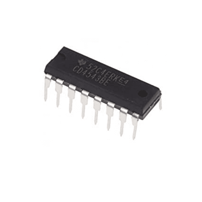
CD4543 - BCD to 7 Segment Decoder IC
The CD4543
IC
is a BCD-to-seven segment latch/decoder/driver IC designed primarily for liquid-crystal display (LCD) applications. It is also capable of driving light-emitting diode (LED), incandescent, gas-discharge, and fluorescent displays. This device is functionally similar and serves as a direct replacement for the CD4056 when pin 7 is connected to VSS. It differs from the CD4056B in that it has a display blanking capability instead of a level-shifting function and requires only one power supply.
When the CD4056 is used in the level shifting mode, two power supplies are required. When the CD4543 is used for LCD applications, a square wave must be applied to the PHASE input and the backplane of the LCD device. For LED applications logic 1 is required at the PHASE input for common-cathode devices; logic 0 is required for common-anode devices (see truth table). The CD4543B is supplied in 16-lead dual-in-line plastic packages (E suffix), 16-lead small-outline packages (M, M96, MT, and NSR suffixes), and 16-lead thin shrink small-outline packages (PW and PWR suffixes).
Pinout:
Pinout of CD4543 - BCD to 7 Segment Decoder IC
Applications:
Instrument display driver
Dashboard display driver
Computer/calculator display driver
Timing device driver (clocks, watches, timers)
₹42.28
Incl. GST (No Hidden Charges)
Backorder Available
₹61.60
Incl. GST (No Hidden Charges)

CD4543 - BCD to 7 Segment Decoder IC
CD4543 - BCD to 7 Segment Decoder IC The CD4543 IC is a BCD-to-seven segment latch/decoder/driver IC designed primarily for liquid-crystal display (LCD) applications. It is also capable of driving …
As low as
₹42.28
₹42.28
₹61.60
Incl. GST (No Hidden Charges)
Backorder Available
7 Segment Led Display (Common…
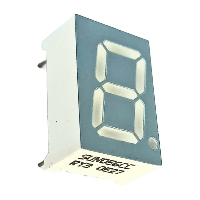
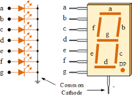
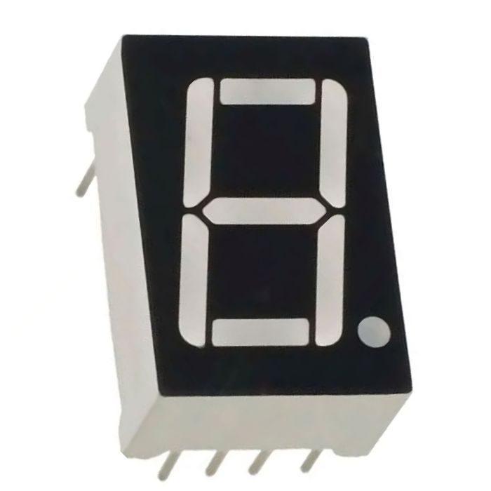
7 Segment Led Display (Common Cathode)
7 Segment Led Display (Common Cathode), is a form of an electronic display device for displaying decimal numerals that is an alternative to the more complex dot matrix displays.
In a common cathode display, all of the LED segment cathode connections are connected to logic "0" or ground. Individual segments are illuminated by applying a "HIGH" or logic "1" signal to the individual Anode terminals via a current limiting resistor (a-g).
Read more:
Implementation of 7 segment LED display Controller on FPGA
Seven-segment displays or ( 7 segment displays) are widely used in digital clocks, electronic meters, basic calculators, and other electronic devices that display numerical information. If you want to use a 7 Segment Led Display in your
Arduino
project, then you will need a few components like
breadboard
,
jumper wires
,
resistors
,
capacitors
and
transistors
.
Iotcart offers at best Common Cathode 7 segment display price in India. Don't settle for anything less than the best— Buy Common Cathode 7 Segment Display now for your next project from Iotcart.
Get
0.96” OLED Display Module
– High-Contrast Blue Screen
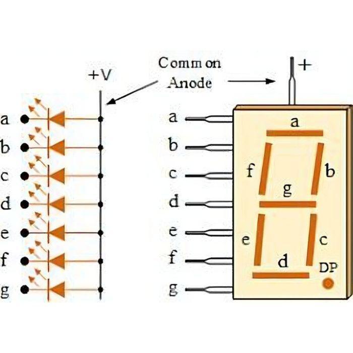
Common Cathode Configuration
Common Cathode 7 Segment Display Truth Table
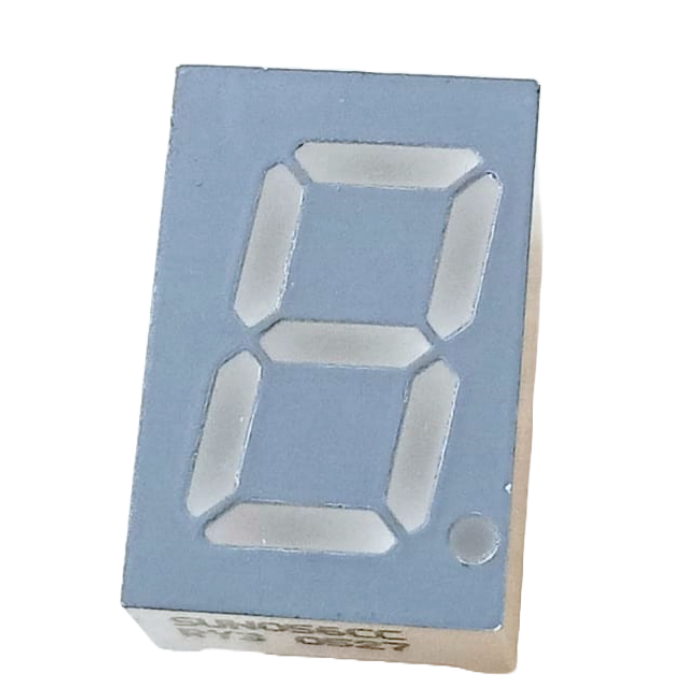
In a common cathode 7 segment display, all the cathodes of the LEDs are linked together. Each LED is accompanied by a current-limiting resistor connected between it and the +VCC. In this configuration, to activate a specific LED, it is connected to +5V. Thus, by connecting inputs a to g to VCC, digits ranging from 0 to 9 can be displayed. For instance, to display the digit 3, LEDs a, b, c, d, and g will emit light, while the remaining LEDs will remain inactive. Consequently, the illuminated LEDs will take the form of the digit 3.
Common Cathode 7 Segment Display Pinout:
Features:
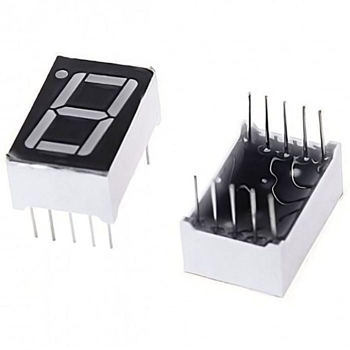
Pin Type: DIP (Dual In-line Package)
Common Cathode Configuration
High Light Intensity Output for optimal viewing
Simple and easy interface with microcontrollers
Applications:
Digital Clocks: Used to display time in a clear and easily readable format.
Electronic Meters: Applied in various measuring instruments for numerical data display.
Basic Calculators: Utilized for showcasing numerical calculations and results.
Counters and Timers: Applied in devices that count or time events, such as countdown timers.
Temperature Displays: Utilized in temperature monitoring systems for numeric temperature readouts.
Numeric Displays: Suitable for any application requiring the display of numeric information.
DIY Electronics Projects: Used by hobbyists and DIY enthusiasts in various electronic projects.
Price Displays: Employed in retail settings for displaying product prices.
Scoreboards: Used in sports and games to display scores and relevant information.
Process Control Systems: Integrated into systems for displaying numeric process parameters.
How to Check 7-Segment Display is Common Anode or Cathode
₹8.90
Incl. GST (No Hidden Charges)
Backorder Available
₹29.40
Incl. GST (No Hidden Charges)
7 Segment Led Display (Common Cathode)
7 Segment Led Display (Common Cathode) 7 Segment Led Display (Common Cathode), is a form of an electronic display device for displaying decimal numerals that is an alternative to the …
As low as
₹8.90
₹8.90
₹29.40
Incl. GST (No Hidden Charges)
Backorder Available
7 Segment Led Display (Common…
7 Segment Led Display
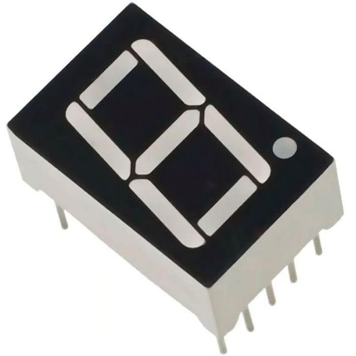
(Common Anode)
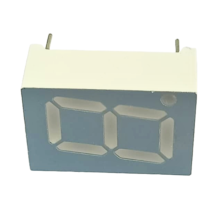
7 Segment Led Display (Common Anode), is a form of an electronic display device for displaying decimal numerals that is an alternative to the more complex dot matrix displays.
The Common Anode (CA)
- In the common anode display, all of the LED segment anode connections are connected to logic "1." Individual segments are illuminated by applying a ground, logic "0" or "LOW" signal to the Cathode of the specific segment via a suitable current limiting resistor (a-g). Common anode displays are more popular in general because many logic circuits can sink more current than they can source. Also, a common cathode display is not a direct replacement in a circuit for a common anode display, and vice versa, because it is equivalent to connecting the LEDs in reverse, and thus no light emission occurs. The specific set of LEDs is forward biased depending on the decimal digit to be displayed.
Seven-segment displays or ( 7 segment displays) are widely used in digital clocks, electronic meters, basic calculators, and other electronic devices that display numerical information. If you want to use 7 Segment Led Display in your
Arduino
project, then you will need a few components like
breadboard
,
jumper wires
,
resistors
,
capacitors
and
transistors
.
₹10.02
Incl. GST (No Hidden Charges)
Backorder Available
₹26.60
Incl. GST (No Hidden Charges)
7 Segment Led Display (Common Anode)
7 Segment Led Display (Common Anode) 7 Segment Led Display (Common Anode), is a form of an electronic display device for displaying decimal numerals that is an alternative to the …
As low as
₹10.02
₹10.02
₹26.60
Incl. GST (No Hidden Charges)
Backorder Available
TM1637 4 Digit 7 Segment LED …
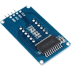
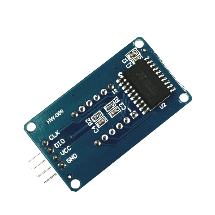
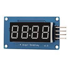
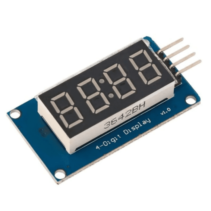
TM1637 4 Digit 7 Segment LED Display
The TM1637 4 digit 7 Segment LED Display is a low-cost solution for displaying
Arduino
project output data. Though the data displayed is limited to numbers, users can also display characters such as A, B, C, and so on. The TM1637 Driver Chip controls the 4 digits on this 7 segment display. This TM1637 4 Bits Digital Tube LED Display Module can be controlled with just two wires.
Also, thanks to the I2C Bus, you can control it with only two wires, freeing up more pins on your Microcontroller for other purposes. The module is a 12-foot clock with four common anode tube (0.36 inch) display module for driver IC TM1637, with only two signal lines allowing the MCU to control four 7-segment digital tubes.
If you want to use this
4 digit
7 segment display module
in your Arduino project, for that you will need few essential components like
jumper wires
breadboard
batteries or power supply
TM1637 4 Digit 7 Segment LED Display pin Diagram
Pinout
:
1
CLK
Clock Input Pin
2
DIO
Data Input/Output Pin
3
VCC
3.3V to 5V power supply Pin
4
GND
Ground Pin
Applications:
Can use as a 4-digit display unit.
Can use as a clock display
DIY clock project.
4 digit display unit.
Electrical/Electronic projects.
The counter project using 7 segment display.
₹54.53
Incl. GST (No Hidden Charges)
Backorder Available
₹96.60
Incl. GST (No Hidden Charges)
TM1637 4 Digit 7 Segment LED Display
TM1637 4 Digit 7 Segment LED Display The TM1637 4 digit 7 Segment LED Display is a low-cost solution for displaying Arduino project output data. Though the data displayed is …
As low as
₹54.53
₹54.53
₹96.60
Incl. GST (No Hidden Charges)
Backorder Available
MAX7219 8x8 LED Dot Matrix Di…
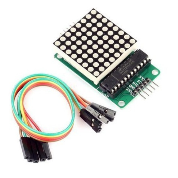
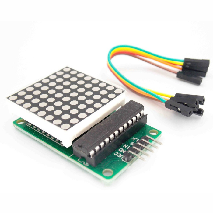
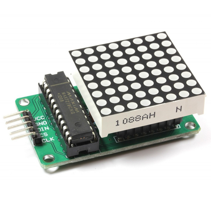
MAX7219 8x8 LED Dot Matrix Display Module
The MAX7219 is a serial input / output common-cathode display driver that is connected to a microprocessor and has an 8-digit 7-segment digital LED display that can also be connected to a bar graph display or 64 separate LEDs. To store each data, an On B BCD encoder with an on-chip, multi-channel scanning loop word drive and an 8 x 8 static RAM is used. To set the current of each LED segment, only one external register is used.
All general-purpose microprocessors can be connected using a simple four-wire serial interface. You can also use this display module in your
Arduino
project as well.
Each data can be addressed in the update, which eliminates the need to rewrite the entire display. MAX7219
Dot Led Matrix display
also allows the user to choose whether to code or not code each data point. The
Dot Led Matrix display
includes a 150A low-power shutdown mode, analogue and digital brightness control, a scan-limit register that allows the user to display 1-8 bits of data, and a let all LED light detection mode. A dot-matrix can be driven with only three IO ports! Flicker-free dot-matrix display! Cascades are supported!
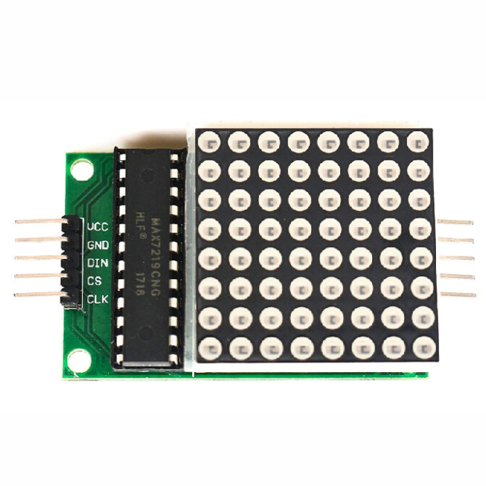
Pin connection:
Dot Matrix Display Module to the Arduino
Vcc
5V
GND
GND
DIN
Pin 12
CS
Pin 10
CLK
Pin 11
Applications:
Bar-Graph Displays
7-Segment Displays
Industrial Controllers
Electronic Panel Meters
LED Matrix Displays
Display symbols, simple graphics, and texts.
₹148.00
Incl. GST (No Hidden Charges)
Backorder Available
₹275.80
Incl. GST (No Hidden Charges)


MAX7219 8x8 LED Dot Matrix Display Module
MAX7219 8x8 LED Dot Matrix Display Module The MAX7219 is a serial input / output common-cathode display driver that is connected to a microprocessor and has an 8-digit 7-segment digital …
As low as
₹148.00
₹148.00
₹275.80
Incl. GST (No Hidden Charges)
Backorder Available
MAX7219 4 in 1 Dot Matrix Dis…
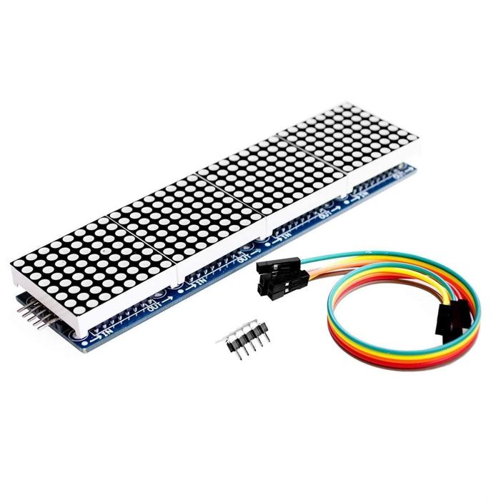
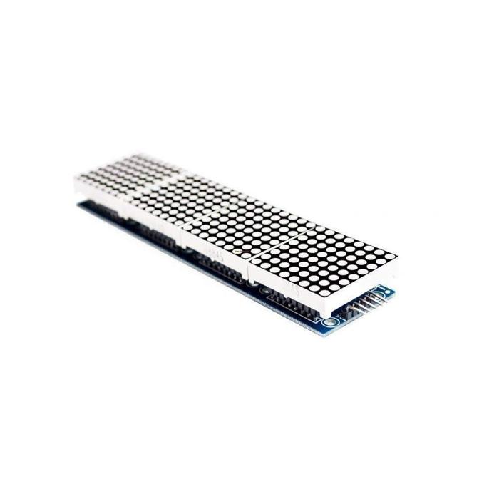
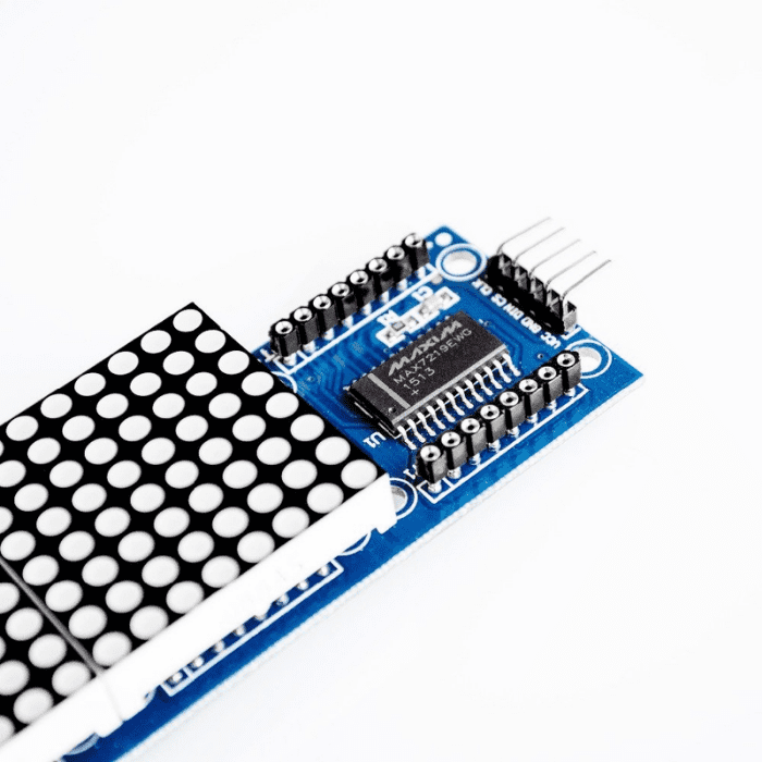
4 in 1 Dot Matrix Module (MAX7219)
This is a Dot Led Matrix Module with a MAX7219 Driver chip. You will be able to add some great cool animation to your upcoming project by using this
dot matrix display
module. The individual module contains 88 LEDs, each of which is precisely controlled by the MAX7219 driver to produce the desired colour pattern. The main advantage of using this is that users will be able to control all 64 LEDs by simply connecting three output communication wires to microcontrollers such as
Arduino
, etc.
It is also very simple to connect the two modules. Simply connect the previous breakout board's output pins to the new module's input pins, and you can connect as many DOT LED
Matrix
Modules to the Arduino as you want!!! The MAX7219 Dot Led Matrix Module is a common-cathode serial input driver that connects microcontrollers to LED matrices. A 4-wire serial interface allows you to connect any common microcontroller to this module. Without refreshing the entire display, each output can be addressed. This module only needs three I/O lines to drive the display, making it ideal for microcontroller projects. To set the segment current of each LED, only one external register is used.
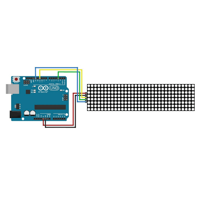
Wiring instructions:
The left side of the module to the input port, the right to an output port
When the control of a single module, simply input port connected to the CPU
When a plurality of cascaded modules, input and output termination CPU, an input terminal of the second output end of the first module a module, the first two modules of the input terminal of the three termination modules, and so on.
Pin connection:
Dot Matrix Display Module to the Arduino
Vcc
5V
GND
GND
DIN
Pin 12
CS
Pin 10
CLK
Pin 11
₹293.76
Incl. GST (No Hidden Charges)
Backorder Available
₹589.40
Incl. GST (No Hidden Charges)
MAX7219 4 in 1 Dot Matrix Display Module
4 in 1 Dot Matrix Module (MAX7219) This is a Dot Led Matrix Module with a MAX7219 Driver chip. You will be able to add some great cool animation to …
As low as
₹293.76
₹293.76
₹589.40
Incl. GST (No Hidden Charges)
Backorder Available
