(0)
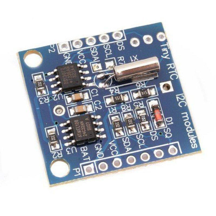
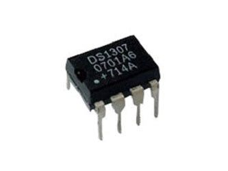
DS1307 Real Time Clock Module
The DS1307 is a low-power clock/calendar with 56 bytes of battery backup SRAM. The clock/calendar provides seconds, minutes, hours, day, date, month and year-qualified data. The end date of each month is automatically adjusted, especially for months with less than 31 days.
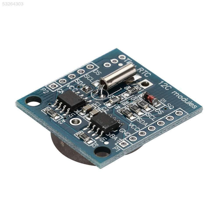
This is Tiny RTC Real Time Clock DS1307 I2C IIC Module for Arduino. It contains a DS1307 real-time clock IC. It’s one of the easiest to use RTCs out there, with Arduino and other libraries or simply use I2C commands to set and retrieve the time and date.
Along with the DS1307 real-time clock, the module also has an Atmel 24C32 EEPROM chip which is handy for storing data without worrying about power loss. There is also space on the board to solder your own DS18B20 temperature sensor.
DS1307 Real Time Clock module is used to track the current time and date. It is generally used in computers, laptops, mobiles, embedded system applications devices, etc. In many embedded systems, we need to put timestamps while logging data i.e. sensor values, GPS coordinates, etc. For getting timestamps, we need to use RTC (Real Time Clock). This module is based on the DS1307 IC from Dallas. It uses a 32.768 kHz clock. And supports I2C Interface.
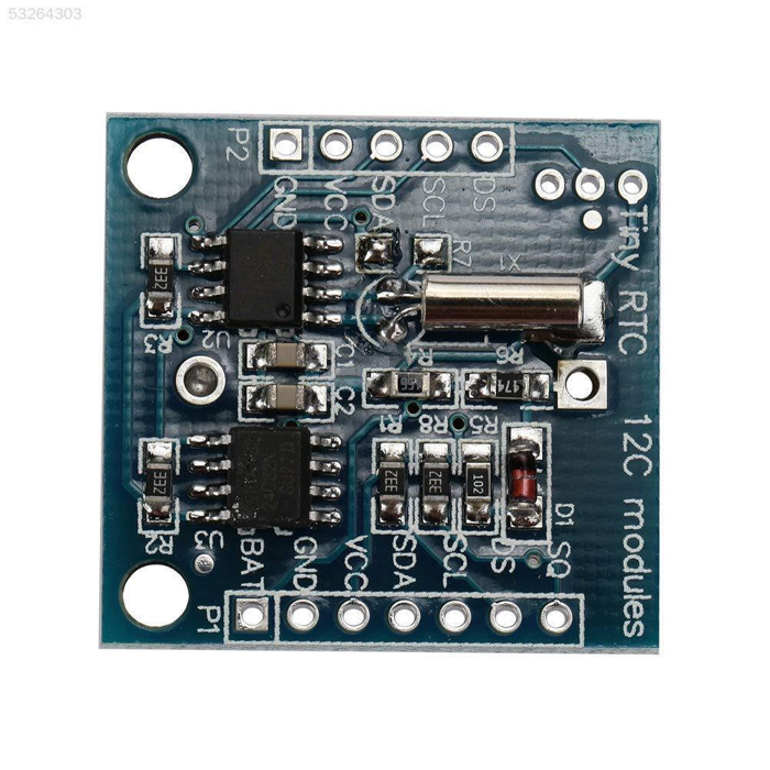
Pinout of DS1307:
Pinout of DS1307 Real Time Clock Module
Pin 1, 2: Connections for standard 32.768 kHz quartz crystal. The internal oscillator circuitry is intended for operation with a crystal having a specified load capacitance of 12.5pF. X1 is the input to the oscillator and can alternatively be connected to an external 32.768 kHz oscillator. The output of the internal oscillator, X2 is drifted if an external oscillator is connected to X1.
Pin 3: Battery input for any standard 3V lithium cell or another energy source. Battery voltage should be between 2V and 3.5V for suitable operation. The nominal write-protect trip point voltage at which access to the RTC and user RAM is denied is set by the internal circuitry as 1.25 x VBAT nominal. A lithium battery with 48mAhr or greater will back up the DS1307 for more than 10 years in the absence of power at 25ºC. UL is recognized to ensure against reverse charging current when utilized as part of conjunction with a lithium battery.
Pin 4: Ground.
Pin 5: Serial data input/output. The input/output for the I2C serial interface is the SDA, which is the open drain and requires a pull-up resistor, allowing a pull-up voltage of 5.5V. Regardless of the voltage on VCC.
Pin 6: Serial clock input. It is the I2C interface clock input and is used in data synchronization.
Pin 7: Square wave/output driver. When enabled, the SQWE bit set to 1, the SQW/OUT pin outputs one of four square-wave frequencies (1Hz, 4 kHz, 8 kHz, and 32 kHz). This is also an open drain and requires an external pull-up resistor. It requires the application of either Vcc or Vb at to operate SQW/OUT, with an allowable pull-up voltage of 5.5V and can be left floating, if not used.
Pin 8: Primary power supply. When the voltage is applied within normal limits, the device is fully accessible and data can be written and read. When a backup supply is connected to the device and VCC is below VTP, read and write are inhibited. However, at low voltages, the timekeeping function still functions.
Package Includes:
1 x DS1307 Real Time Clock Module
Specifications:
Operating Voltage
5V
Battery
IR2032
Dimensions
2.7 x 2.8cms
Weight
5 grams
₹37.39
₹46.74
Incl. GST